ZIQI Compressor For Global Energy Saving, Welcome To Contact Us.  008615026767628
Language
ZIQI Compressor For Global Energy Saving, Welcome To Contact Us. 008615026767628

Compressed Air Systems Engineer
ZIQI Compressor Group · Updated October 2026
Pressure drop (ΔP) is the continuous loss of compressed air pressure as it travels from the compressor discharge to the point of use, caused by internal pipe friction, flow restrictions, and inline treatment components. A well-designed industrial pneumatic system should maintain a total pressure drop of 1.0 to 1.5 bar. When pressure drops exceed 2.0 bar, the compressor must work significantly harder, incurring a 6% to 7% electrical energy penalty for every 1 bar of over-pressurization. Systematically diagnosing this requires measuring differential pressure across filters and dryers, identifying leaks, and utilizing the Darcy-Weisbach equation to evaluate if the main header piping is severely undersized for the velocity of the air flow.
Losing pressure between your compressor and your tools means paying more electricity for air you never use. As a leading air compressor manufacturer in China, ZIQI has documented the six most common root causes of pressure drop and built this diagnostic framework to help plant engineers fix them without guesswork.
In an ideal facility, the air pressure leaving the compressor room would exactly match the pressure arriving at a pneumatic cylinder 200 meters away. In reality, fluid dynamics dictate that moving air through pipes, valves, and filters inherently dissipates energy as friction. This loss of potential energy manifests as a drop in gauge pressure.
Pressure drop is not merely a performance inconvenience; it is a massive financial drain. If an assembly line impact wrench requires 6.0 bar to torque bolts correctly, but the piping network causes a 2.5 bar pressure drop, the compressor room must be set to generate 8.5 bar.
The thermodynamics of compression dictate that for every 1 bar of increased discharge pressure, the compressor motor consumes approximately 6% to 7% more electrical energy. Over a 6,000-hour annual operating cycle on a 160 kW compressor, compensating for a poorly designed, restrictive pipe network can easily cost tens of thousands of dollars in wasted electricity. Furthermore, artificially elevating the system pressure accelerates wear on the airend bearings and exacerbates the volume of air lost through existing leaks.
To truly diagnose and eliminate pressure drop, engineers rely on classical fluid mechanics. The primary mathematical model for calculating friction loss in a closed pipe is the Darcy-Weisbach equation.
The Darcy-Weisbach Equation: ΔP = f · (L/D) · (ρv²/2)
Where:
ΔP = Pressure drop (Pa)
f = Darcy friction factor (dimensionless, determined by the Moody Chart depending on pipe roughness and Reynolds number)
L = Total equivalent length of the pipe (m)
D = Internal diameter of the pipe (m)
ρ = Fluid density of the compressed air (kg/m³)
v = Fluid velocity (m/s)
The D⁵ Rule: Because velocity (v) is equal to volumetric flow rate divided by the cross-sectional area of the pipe (πD²/4), substituting velocity into the equation reveals that pressure drop is inversely proportional to the fifth power of the diameter (D⁵).
Diagnostic Example: Consider a 100m pipe run at 7 bar, delivering 500 Nm³/h, with an internal pipe diameter of 50mm. The calculated ΔP is approximately 0.4 bar. If the facility expands and a contractor mistakenly extends the line using 40mm pipe (a 20% reduction in diameter), the ΔP does not just increase by 20%. The ΔP jumps to 1.2 bar—a 3× exponential increase in pressure loss due to the severe velocity spike and turbulent flow.
Additionally, the L (Length) variable must account for "equivalent length." Every 90° elbow, T-junction, or ball valve introduces turbulence. In engineering calculations, a standard 90° elbow creates the same friction loss as adding a straight pipe length equivalent to 30 times the pipe's internal diameter (30D).
Before troubleshooting, it is essential to know what constitutes "normal" friction. Even perfectly engineered, brand-new treatment equipment introduces resistance. The table below outlines the acceptable ΔP budget for a standard industrial air system running at optimal velocity (below 6 m/s in main headers).
| System Component | Acceptable ΔP (bar) | Status |
|---|---|---|
| Air-cooled After-cooler | 0.1 – 0.2 | Normal |
| Refrigerated Air Dryer | 0.2 – 0.3 | Normal |
| Desiccant Air Dryer | 0.3 – 0.5 | Normal |
| Coalescing Pre-Filter (Oil removal) | 0.1 – 0.3 | Normal |
| Particulate After-Filter (Dust removal) | 0.1 – 0.2 | Normal |
| Main Header Piping | 0.3 – 0.5 | Normal |
| Branch Lines + End-Use Connections | 0.2 – 0.5 | Normal |
| Total Acceptable System ΔP | 1.0 – 1.5 bar | Healthy System |
| System Degradation Threshold | > 2.0 bar | Requires Diagnosis |
When total system pressure drops exceed 2.0 bar, the compressor is masking a severe structural or maintenance failure. The following six root causes account for the vast majority of industrial pressure loss.
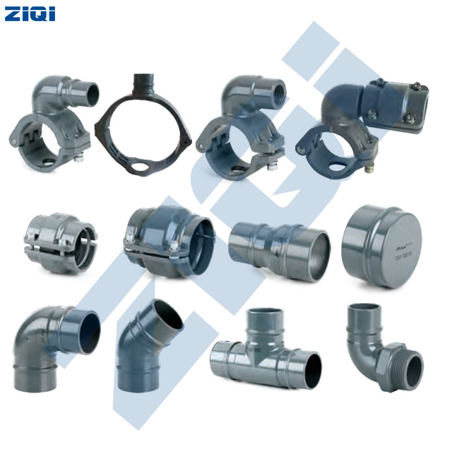
Physics: As dictated by the Darcy-Weisbach D⁵ relationship, pushing a high volume of air through a narrow pipe forces the velocity to skyrocket, shifting the fluid dynamics from smooth laminar flow to chaotic, high-friction turbulent flow (high Reynolds number).
Symptom: The compressor is running fully loaded and generating high pressure in the compressor room, but the end-of-line pressure is severely depleted.
Diagnosis: Install calibrated pressure gauges at the beginning and end of the main header run. If the pressure drops more than 0.1 bar per 100 meters of straight pipe, the diameter is too small for the current flow rate.
Solution: Upgrade the main header to a larger diameter, or install a parallel ring-main configuration to split the volumetric flow and reduce velocity.
Physics: Coalescing and particulate filters utilize dense micro-glass matrices. As they capture oil aerosols and dust, the open pore space diminishes. The air is forced through smaller channels, drastically increasing localized resistance.
Symptom: Gradual decline in plant pressure over several months without any new equipment being added to the factory floor.
Diagnosis: Check the differential pressure indicator mounted on top of the filter housings. Alternatively, manually measure the pressure directly upstream and downstream of the filter bank. A ΔP > 0.5 bar across a single filter indicates critical saturation.
Solution: Replace filter elements strictly based on differential pressure readings, not just calendar age. Verify that the upstream compressor is not passing excessive bulk oil.
Physics: Desiccant twin-tower dryers force air through deep beds of activated alumina. If the flow rate pushed through the dryer exceeds its nominal capacity, or if the desiccant beads have broken down into dust (channeling), the internal friction multiplies.
Symptom: A massive localized pressure drop specifically localized inside the compressor room treatment skid.
Diagnosis: Measure the pressure directly at the dryer inlet and outlet ports while the system is at peak flow. Normal drop is 0.3 bar; a drop exceeding 0.8 bar indicates an undersized or structurally degraded dryer bed.
Solution: Size dryers based on actual maximum volumetric flow, ensuring inlet temperature and pressure correction factors (per ISO 7183) have been correctly applied during selection.
Physics: Leaks do not just waste air; they artificially increase the total volumetric flow demand (Q) traversing the pipes. Because velocity (v) increases to feed the leaks, the pressure drop increases exponential per the v² variable in the Darcy-Weisbach equation.
Symptom: The compressor never unloads, even during low-production shifts, and distant sectors of the plant constantly complain of low pressure.
Diagnosis: Conduct an Ultrasonic Leak Detection audit during non-production hours. Listen for high-frequency hissing at fittings, quick-disconnects, and aging pneumatic hoses.
Solution: Implement a continuous leak-tagging and repair program. Replacing cheap, leaking polyurethane hoses with rigid drops instantly restores localized pressure.
Physics: Every sharp 90° elbow, harsh T-junction, and sudden diameter reduction creates violent turbulence, stripping kinetic energy from the air stream. A poorly designed distribution manifold with ten sharp elbows can generate more friction than 100 meters of straight pipe.
Symptom: Pressure drops severely across a relatively short physical distance.
Diagnosis: Perform a visual audit of the piping schematics. Calculate the "Equivalent Length" of all fittings.
Solution: Re-engineer critical path piping. Replace sharp 90° elbows with long-radius sweeping bends. Use directional Y-branches instead of dead-head T-junctions.
Physics: If air dryers fail, water vapor condenses into liquid water inside the cold piping network. This liquid pools in low-lying sections of the pipe, physically obstructing the cross-sectional area and acting as an unpredictable flow restrictor.
Symptom: Erratic pressure fluctuations accompanied by water spraying from end-use pneumatic exhaust ports.
Diagnosis: Open manual drain valves at the lowest points of the piping network. If significant water or oil sludge discharges, the pipe's internal diameter has been severely compromised by liquid buildup.
Solution: Install automated zero-loss drain traps at all low points. Resolve the upstream dryer failure that allowed moisture into the network. Pitch horizontal pipes at a 1% to 2% gradient toward drain points.
Pressure drop diagnostics often overlap with other thermal and contamination issues. For compressor overheating diagnostics, see the rotary screw compressor overheating guide. For oil carryover issues affecting downstream pressure, see the air compressor oil carryover diagnostics guide.
| Observed Symptom | Probable Root Cause | Engineering Solution |
|---|---|---|
| Compressor is at 8 bar, but plant end-line is at 5 bar. | Severe overall system restriction. Piping is drastically undersized for the flow velocity. | Calculate Darcy-Weisbach velocity. Upgrade main header pipe diameter or loop the dead-end header into a ring main. |
| Sudden 0.8 bar drop localized entirely across the filter bank. | Coalescing filter elements are fully saturated with oil aerosol and particulate dust. | Replace filter elements immediately. Verify upstream compressor is not exhibiting severe oil carryover. |
| Pressure is fine when plant is idle, but collapses when shifts start. | Insufficient storage capacity (receiver tanks) causing dynamic flow restrictions during peak spikes. | Install additional dry receiver tanks close to high-demand applications to buffer instantaneous flow spikes. |
| Hissing sounds audible near manifolds; compressor rarely unloads. | Extensive volumetric leaks artificially accelerating pipe air velocity and inducing massive friction. | Conduct an ultrasonic leak audit. Repair aging quick-disconnects, threaded fittings, and blown hoses. |
| Pressure drops 0.5 bar across a relatively short 10m pipe section. | Poor architectural layout featuring multiple sharp 90° elbows, T-junctions, or sudden reducers. | Re-pipe the section utilizing sweeping long-radius bends and 45° directional Y-branches to smooth air flow. |
| Water spraying from end-use tools; fluctuating pressure readings. | Refrigerated dryer failure has allowed bulk water to condense and pool inside the pipe, blocking flow. | Repair air dryer. Open all low-point drain valves to purge liquid. Install automatic zero-loss drains. |
Plant maintenance teams can effectively manage basic pressure drop issues—such as replacing saturated filter elements, fixing audible pneumatic leaks, and draining waterlogged receiver tanks. Routine preventative maintenance eliminates the vast majority of creeping pressure losses.
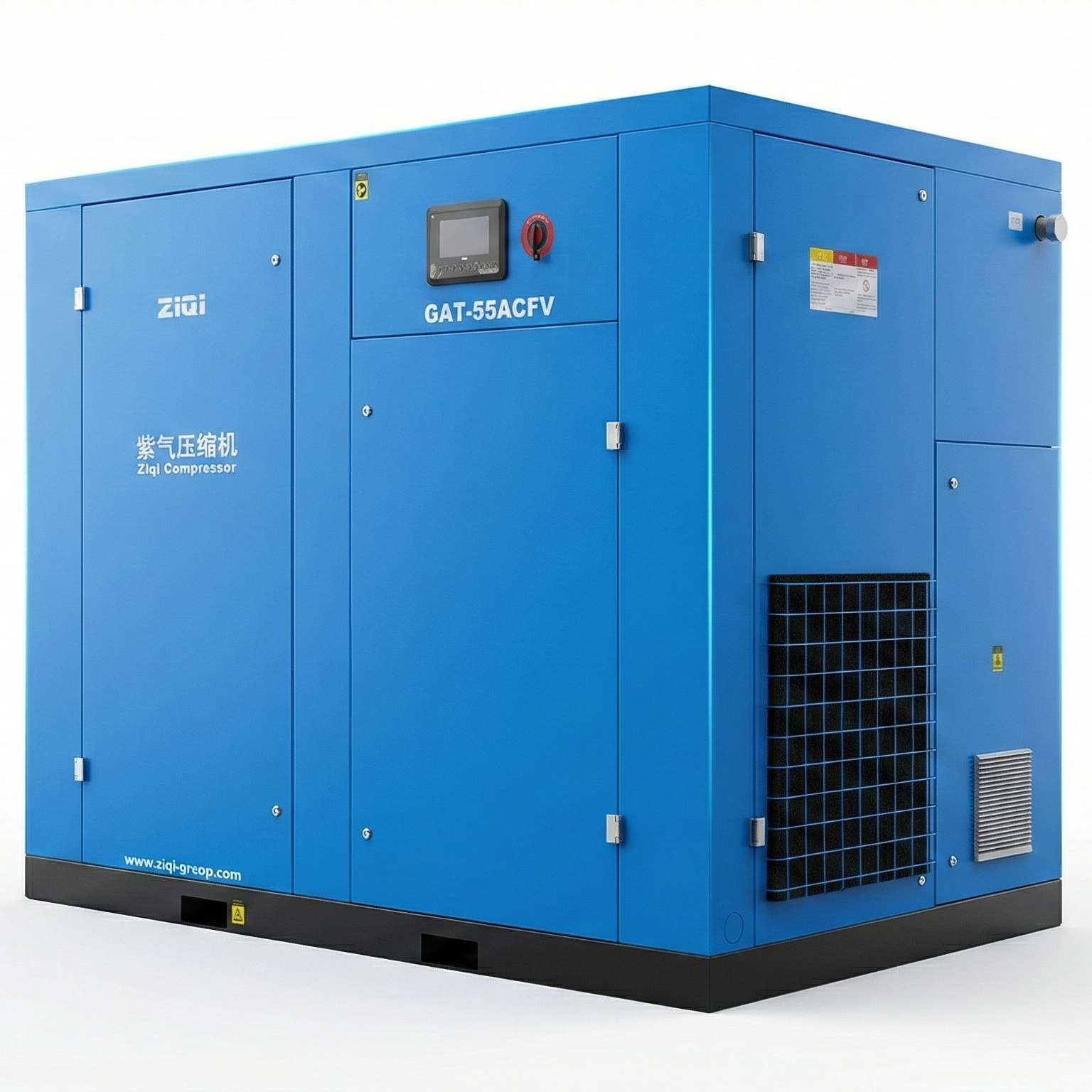
However, if you have verified that all filters are clean, dryers are correctly sized, and leaks are minimized, yet the facility still suffers a 2.0+ bar total pressure drop, the core issue is systemic. Redesigning an undersized, highly turbulent piping network requires professional fluid dynamics calculation. Consulting a compressed air systems engineer is necessary to properly size a new aluminum or stainless steel ring main, calculate the required volume for point-of-use receiver tanks, and optimize the compressor room sequencing controls to match the true pressure profile of the facility.
In a properly engineered industrial compressed air system, the total acceptable pressure drop from the compressor discharge flange to the furthest point of use should be between 1.0 and 1.5 bar (14.5 to 22 PSI). This budget accounts for the necessary resistance through after-coolers, dryers, coalescing filters, and the friction inherent in the main piping network. Any total drop exceeding 2.0 bar indicates severe system degradation or undersized infrastructure.
To accurately measure pressure drop across a specific treatment component, the system must be running at peak dynamic flow (during normal production). Install calibrated, matching pressure gauges immediately at the inlet port and the outlet port of the filter or dryer. Subtract the outlet reading from the inlet reading. A healthy filter should show a drop of 0.1 to 0.3 bar. If the drop exceeds 0.5 bar, the element is saturated.
Pressure drop forces the compressor to over-pressurize the air to compensate for the downstream losses. The thermodynamics of compression dictate an exponential energy penalty: for every 1 bar (14.5 PSI) of increased discharge pressure required at the compressor, the electric motor consumes approximately 6% to 7% more energy. Eliminating a 1.5 bar unnecessary pressure drop yields an instant 10% reduction in electrical power consumption.
Based on the Darcy-Weisbach fluid dynamics equation, pressure drop in a pipe is inversely proportional to the fifth power of the internal diameter (D&sup5;). This is an exponential relationship. Reducing a pipe's diameter by just 20% (e.g., from 50mm to 40mm) forces the air velocity to spike, creating severe turbulence that increases the pressure drop by roughly 300%. Properly oversized piping is the most effective defense against friction loss.
Yes. While leaks directly waste compressed air, they also artificially increase the total volume of air moving through the piping network. Because pressure drop is proportional to the square of the air velocity (v²), the increased speed required to feed massive downstream leaks generates exponential friction against the pipe walls, dragging down the overall static pressure available for production machinery.
You should upgrade the piping infrastructure if you measure a pressure drop exceeding 0.1 bar per 100 meters of straight pipe run, indicating the air velocity has surpassed optimal limits (typically > 6 m/s). Additionally, if your current network utilizes aging carbon steel pipes that are internally scaling and rusting, upgrading to smooth-bore aluminum or 304 stainless steel piping will significantly reduce the internal friction factor and eliminate secondary contamination.
Need engineering support for persistent pressure drop issues? ZIQI provides system analysis and component sizing consultation for compressed air networks.
QUICK LINKS
PRODUCTS
CONTACT US
 Email : inquiry@ziqi-group.com
 Tel: +86-15026767628
 Add:Building 2, No. 205, Jianding Road, Fengjing Town, Jinshan District, Shanghai City.China
PLEASE CONTACT US.

ZIQI Compressor (Shanghai) Co., Ltd
Copyright © 2026 ZIQI Compressor (Shanghai) Co., Ltd - All rights reserved.

